













Industry Applications
Rogers Substrate Material Selection Guide: RO4003C vs RO4350B vs RO5880 Comparison
Jul
An engineer sends over a drawing marked “Rogers, 50 ohms.”
That’s it.
No exact laminate grade. No copper profile. No test frequency. Nobody says whether the impedance calculator used process Dk or design Dk, and the surface finish is simply marked ENIG—as though nickel suddenly stops affecting RF current because it appears in a standard fabrication note.
History always keeps repeating itself.
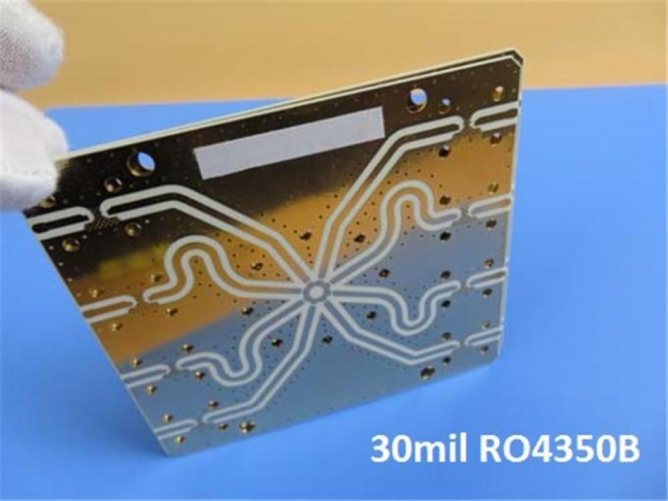
RO4003C, RO4350B, and RT/duroid 5880 are all sold as high-frequency materials, but they solve different problems. RO5880 wins the raw dielectric-loss contest. RO4350B is usually easier to push through commercial multilayer production. RO4003C often sits in the sensible middle ground for engineers who need RF performance but don’t need a UL 94 V-0 rating.
That sounds straightforward.
It isn’t.
A Rogers PCB material never operates as an isolated square of laminate. It becomes part of a physical transmission structure containing etched copper, glass reinforcement, plated holes, solder mask, surface finish, connectors, launches, vias, bondply and manufacturing tolerances. Any material comparison that ignores those details is incomplete—sometimes dangerously so.
The Practical Answer First
Here’s how I’d shortlist them before opening a field solver:
Choose RO4003C when the design needs stable RF performance and FR-4-like processing, but flame-retardant certification isn’t mandatory.
Choose RO4350B for commercial RF products where manufacturing consistency, multilayer compatibility and UL 94 V-0 matter alongside electrical performance.
Choose RT/duroid 5880 when insertion loss, broadband behavior, antenna efficiency or phase stability matters enough to justify PTFE processing.
The published electrical gap is real. RO4003C has a process Dk of 3.38 ±0.05 and a typical dissipation factor of 0.0027 at 10 GHz. RO4350B is listed at 3.48 ±0.05 and 0.0037. RT/duroid 5880 drops to Dk 2.20 ±0.02 and Df 0.0009.
Does that make RO5880 best?
Only when dielectric loss is actually the problem you’re paying to solve.
RO4003C vs RO4350B vs RO5880: Technical Data
| Property | RO4003C | RO4350B | RT/duroid 5880 |
|---|---|---|---|
| Material system | Hydrocarbon ceramic, woven glass | Hydrocarbon ceramic, woven glass | PTFE, random glass microfiber |
| Process Dk | 3.38 ±0.05 | 3.48 ±0.05 | 2.20 ±0.02 |
| Typical design Dk | 3.55 | 3.66 | 2.20 |
| Df at 10 GHz | 0.0027 | 0.0037 | 0.0009 |
| Thermal conductivity | 0.71 W/m·K | 0.69 W/m·K | 0.20 W/m·K |
| Z-axis CTE | 46 ppm/°C | 32 ppm/°C | 237 ppm/°C |
| Moisture absorption | 0.06% | 0.06% | 0.02% |
| Typical copper peel strength | 1.05 N/mm | 0.88 N/mm | 5.5 pli, approximately 0.96 N/mm |
| Flame rating | Non-flame-retardant / no V-0 rating | UL 94 V-0 | UL 94 V-0 |
| Lead-free process compatible | Yes | Yes | Yes |
| Relative fabrication difficulty | Low to moderate | Low to moderate | High |
| Best general fit | Cost-controlled RF | Commercial multilayer RF | Ultra-low-loss microwave and antennas |
The awkward number is 237 ppm/°C.
That’s the published Z-axis CTE for RT/duroid 5880, compared with 46 ppm/°C for RO4003C and 32 ppm/°C for RO4350B. It doesn’t mean every RO5880 plated hole will fail; that would be nonsense. It does mean thermal cycling, PTH structure, material thickness and multilayer construction deserve more attention than they might on an ordinary RO4350B board.
The datasheet winner suddenly looks less simple.
Df Is Only One Piece of Insertion Loss
People love comparing 0.0037 with 0.0009.
Fair enough. It’s a large difference.
But a fabricated transmission line also loses energy through conductor resistance, copper roughness, narrow geometry, discontinuities, surface finish and imperfect impedance matching. On thin substrates, a 50-ohm microstrip trace normally becomes narrower; that can drive conductor loss upward even when the dielectric itself is excellent.
So I get suspicious when a design team wants to change laminate but hasn’t specified the copper foil.
Rogers’ RO4000 LoPro materials exist for a reason: smoother copper can reduce conductor loss while retaining the RO4000 dielectric system.
The practical lesson? A well-built high-frequency RF PCB with controlled impedance may outperform a more expensive laminate choice that was paired with rough copper, an unnecessarily narrow trace and a lossy RF launch.
And then there’s ENIG.
Nickel under the gold finish can increase RF conductor loss. I’m not saying ENIG should never be used—it’s common, convenient and often perfectly acceptable—but leaving the finish out of the loss analysis while debating Df to four decimal places is engineering theatre.
Process Dk and Design Dk Aren’t the Same Number
This catches people quietly.
Process Dk is used mainly for material specification and quality control under a defined test method. Design Dk is intended to better represent the value an engineer should use when modelling a transmission structure.
The two numbers can differ.
RO4003C, for example, has a published process Dk of 3.38 but a typical design Dk around 3.55. RO4350B is commonly listed at 3.48 process Dk and about 3.66 design Dk. Even thickness matters: the 4 mil RO4350B construction carries a process Dk of 3.33 ±0.05 rather than the familiar 3.48 figure.
That’s not trivia when the line is short, the tolerance is loose and the frequency is modest.
At 24 GHz or 77 GHz? Different story.
The RFQ should state:
- Material grade and laminate thickness
- Dk used in the original calculation
- Finished copper thickness
- Target impedance and tolerance
- Test frequency
- Coupon requirements
- Whether the PCB manufacturer may adjust trace width
- Surface finish across the RF path
“50 ohms required” leaves too much unsaid.
Why RO4000 Materials Are Easier to Build
RO4003C and RO4350B are ceramic-filled hydrocarbon thermoset laminates reinforced with woven glass. They aren’t PTFE boards pretending to be FR-4.
Still, their manufacturing route feels familiar.
Rogers states that RO4000 laminates can use standard FR-4-like circuit-processing techniques, and its fabrication guidance covers normal multilayer operations such as imaging, drilling, desmear, metallization, routing and V-scoring.
RO5880 behaves differently. It’s a PTFE composite reinforced with randomly oriented glass microfibers, chosen for low loss and dielectric uniformity—not because fabricators enjoy handling it. Rogers itself describes RO4003C as friendly to high-volume fabrication and suited to high-layer-count boards using FR-4-like processing.
That distinction shows up in real quotes.
A factory may need to consider different drill parameters, hole-wall preparation, dimensional movement, multilayer bonding, routing quality and panel handling for PTFE material. Some factories handle it well. Some claim they do.
Ask for evidence.
For mixed digital and RF products, I often prefer a hybrid stack: Rogers laminate on the RF-critical layers and high-Tg FR-4 elsewhere. It fits products such as multilayer embedded control main boards, where only part of the board genuinely benefits from premium low-loss material.
HDI Makes Material Selection Messier
A thin Rogers core looks attractive in a simulation.
Then someone adds blind vias, laser microvias, stacked structures and sequential lamination.
Now the laminate choice can’t be separated from the build sequence. Bonding temperature, dielectric thickness after lamination, registration, laser-via quality and resin movement all enter the discussion. A designer moving toward an HDI PCB manufacturing structure should confirm the exact stack-up with the fabricator before final routing—not after the Gerbers are released.
Frankly, this is where “drop-in material replacements” become expensive.
Same Dk doesn’t mean same process.
RO5880 Is Low-Loss, Not High-Thermal
This one causes confusion.
RT/duroid 5880 has published thermal conductivity around 0.20 W/m·K. RO4003C and RO4350B are roughly 0.71 and 0.69 W/m·K.
So yes, RO5880 reduces dielectric loss.
No, it doesn’t magically spread heat from a power amplifier.
A high-power RF design may still need thick copper, thermal-via arrays, copper coins, a machined carrier or a separate high-thermal-conductivity IMS PCB. Low electrical loss and strong thermal conduction aren’t interchangeable features, even though they’re often discussed in the same design meeting.
RO4003C vs RO4350B
RO4003C has the lower published Df: 0.0027 versus 0.0037 at 10 GHz.
RO4350B fights back elsewhere.
It carries UL 94 V-0 recognition and has lower published Z-axis expansion. That makes it a comfortable default for commercial RF equipment that must survive normal production, assembly and compliance review—not merely pass an RF simulation. Rogers positions RO4003C for cost-sensitive microwave and RF designs, while RO4350B combines low-loss behavior with standard epoxy-glass-style processing.
I’d use RO4003C when:
- UL 94 V-0 isn’t required
- The lower Df offers measurable benefit
- Cost sensitivity is real
- The chosen thickness is readily available
- The board structure is reasonably straightforward
I’d lean toward RO4350B when:
- V-0 is required
- The board is multilayer or hybrid
- PTH reliability has more weight
- Production repeatability matters
- Procurement wants a widely recognised commercial RF option
It’s not glamorous advice.
It works.
RO4350B vs RO5880
RO5880’s Df of 0.0009 is less than one-quarter of RO4350B’s 0.0037 value at 10 GHz. That’s enough to matter in long transmission lines, antenna feed networks, broadband circuits and phase-sensitive microwave structures.
Yet RO4350B is easier to place inside a normal commercial PCB.
Choose RO5880 when:
- The RF path is long
- Insertion-loss margin is tight
- Antenna efficiency drives product performance
- Phase consistency matters
- Broadband or millimeter-wave performance has been modelled
- A qualified PTFE fabricator is available
Choose RO4350B when:
- RF traces are relatively short
- The design already passes its loss budget
- Digital and power circuitry occupy most of the board
- Multilayer yield matters
- The project needs a practical route into volume production
RO5880 is a specialist.
RO4350B is the all-rounder.
Matching the Material to the Application
For GPS L1 at 1.57542 GHz, an all-RO5880 board may be difficult to justify unless the product uses a long antenna feed, tight phase control or a particularly demanding low-noise architecture. A mixed GPS, FPGA and LCD control PCB prototype can use Rogers material only around the RF section while FR-4 carries processing, display and power functions.
For cellular infrastructure, power amplifiers and many commercial antenna products, RO4350B is a solid first candidate. RO4003C becomes attractive when flame rating isn’t part of the specification.
For wideband antennas, microwave filters, couplers and feed networks, RO5880’s low Dk and low Df begin to earn their cost. Its lower Dk can also produce wider 50-ohm traces at the same dielectric thickness—which may help conductor loss.
At 77 GHz, though, stop treating this as a laminate-only decision. Copper roughness, etch accuracy, local trace-width variation, solder-mask clearance, connector launch and reference-plane continuity can dominate a result that looked perfect in a simple calculator.
Cost Is More Than the Laminate Price
The material sheet price gets attention because it’s visible.
Yield is quieter.
A finished Rogers PCB quote may include non-standard laminate thicknesses, copper type, bonding material, panel waste, special drilling, hole treatment, controlled routing, impedance coupons, loss testing, longer process time and the fabricator’s risk allowance.
That’s why RO5880 sometimes looks acceptable at raw-material level but expensive at finished-board level.
Availability also matters. In June 2024, Rogers announced plans to wind down advanced circuit-material manufacturing at its Evergem, Belgium facility by mid-2025 while continuing customer support through operations in China and the United States. The company estimated annual operating-profit improvement of $7–9 million and associated charges of $18–28 million.
Rogers’ Advanced Electronics Solutions sales were $112.2 million in Q3 2024, compared with $126.3 million in Q3 2023. The company reported softer demand in several segments, partly offset by higher aerospace, defence and wireless-infrastructure sales.
That doesn’t prove a shortage.
It does support one boring but useful habit: confirm the exact grade, core thickness and copper construction before freezing the design.
How to Choose Rogers PCB Material
I’d make the decision in this order:
- Define operating frequency, line length, bandwidth and power.
- Build a total loss budget—not just a dielectric-loss estimate.
- Check whether UL 94 V-0 is mandatory.
- Review PTH structure, thermal cycling and Z-axis CTE.
- Confirm available thicknesses and copper foil.
- Ask the factory about actual experience with the exact material.
- Build and measure a representative prototype.
Don’t approve “Rogers or equivalent” casually.
An alternative with similar Dk may have different Df, CTE, copper adhesion, reinforcement, thermal conductivity, thickness tolerance, flame rating and bonding behaviour. That isn’t equivalent. It’s merely similar in one column.
Frequently Asked Questions
What Is the Best Rogers Material for RF PCB Design?
The best Rogers material is the grade whose dielectric loss, Dk tolerance, thermal expansion, flame rating, thickness availability, copper construction and fabrication process match the board’s actual frequency, geometry, power, compliance requirements and production volume—not automatically the laminate with the lowest published dissipation factor.
For many commercial multilayer RF products, RO4350B is the safest starting point. RO4003C suits cost-controlled applications without a V-0 requirement. RO5880 makes sense when measured RF performance justifies PTFE processing.
What Is the Main Difference Between RO4003C and RO4350B?
RO4350B provides UL 94 V-0 flame performance and lower published Z-axis thermal expansion, while RO4003C offers a lower dissipation factor and is positioned as a cost-sensitive RF material; both belong to the RO4000 hydrocarbon-ceramic family and can use processing methods familiar to FR-4 PCB manufacturers.
In plain language: RO4003C is attractive for electrical value. RO4350B is easier to defend in a commercial product review.
Is RO5880 Better Than RO4350B?
RO5880 is better when extremely low dielectric loss, low Dk, broadband response or phase stability matters more than fabrication ease, multilayer yield, thermal conductivity and finished-board cost; RO4350B is generally better when the product must balance RF performance with practical, repeatable commercial manufacturing.
So the answer depends on what “better” means.
Electrically? Often RO5880.
Operationally? Often RO4350B.
Can Rogers Material Be Combined With FR-4?
A Rogers-and-FR-4 hybrid PCB uses Rogers laminate on RF-critical layers and conventional FR-4 or high-Tg FR-4 on digital, power, control or structural layers, reducing material cost while retaining low-loss performance where the electric fields and sensitive transmission lines actually require it.
The stack still needs review for bondply compatibility, resin flow, CTE mismatch, finished thickness and impedance movement.
How Do I Choose Between RO4003C, RO4350B and RO5880?
Choose among RO4003C, RO4350B and RO5880 by comparing total insertion loss, operating frequency, line geometry, flame-rating requirements, thermal cycling, plated-hole structure, copper profile, laminate availability, production quantity and fabricator experience rather than selecting a material from Dk and Df values alone.
My shorthand remains:
RO4003C for value.
RO4350B for balance.
RO5880 for verified low-loss need.
Send the Stack-Up, Not Just the Material Name
For a meaningful material review, send the Gerber files, proposed stack-up, operating frequency, target impedance, maximum insertion loss, copper specification, surface finish, finished board thickness, quantity and certification requirements.
A datasheet helps.
A measured prototype decides.
