

Industry Applications
ICT vs Functional Testing: Which You Need
Jun
Testing gets political.
I have watched buyers, engineers, and factory teams argue over ICT vs functional testing as if one method can magically protect every shipment, every relay, every BGA joint, every MOSFET gate, and every firmware-loaded control PCB from failure. It cannot. So why do so many RFQs still ask for “100% test” without saying what kind of failure they want to catch?
That phrase is dangerous.
In PCB testing, “100% test” can mean bare PCB electrical test, AOI inspection, in-circuit testing, functional circuit test, power-on validation, burn-in, firmware programming, or a custom jig that only the original engineer understands. I am not saying this to sound clever. I am saying it because vague test language costs real money, especially when a product moves from 20 prototypes to 2,000 pieces and nobody agreed what “pass” actually means.
The hard truth: ICT is better at finding manufacturing defects. Functional testing is better at proving the product behaves like a product.
That is the whole fight.
The Dirty Difference Between ICT and Functional Testing
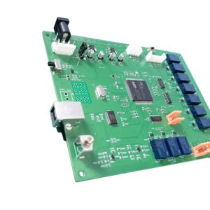
ICT, or in-circuit testing, checks the assembled PCB at component and net level. As a hardware-contact-based testing method, it works by using a probe fixture (typically a pin bed structure) to capture electrical signals from test points. By evaluating the electrical characteristics between these nodes, the system can not only identify common anomalies such as open circuits and short circuits, soldering defects, and the assembly status of integrated circuits and diodes, but also perform quantitative resistance and capacitance measurements, while also conducting basic electrical tests at low voltages and low currents.
To ensure that assembled PCBA units meet actual operational requirements, functional testing must be incorporated into the manufacturing process. This method involves placing the entire circuit board in a simulated end-product environment, powering it on, and loading the firmware to comprehensively verify its logic execution and peripheral drive capabilities—ranging from simple button triggers, voltage output, and relay switching to complex sensor readings, Bluetooth communication, and LCD screen updates—thereby fully assessing the circuit board’s functional integrity.
Simple? no.
ICT asks, “Was this PCBA assembled correctly?”
Functional testing asks, “Does this PCBA do the job?”
Due to fundamental differences in testing mechanisms, the performance of PCBA in ICT and functional testing cannot be equated. Components that pass In-Circuit Testing (ICT) may still experience functional failure under real-world conditions due to firmware logic errors, poor Bluetooth antenna matching, abnormal relay operation, or power supply collapse under load. Similarly, a passing result in functional testing often obscures the true health of the underlying hardware, allowing soldering defects, incorrect capacitor specifications, marginally functional circuits, and potentially hazardous replacement components to slip through undetected,ultimately leading to premature product failure at the customer’s end.
I know this sounds uncomfortable. It should.
Why ICT Exists: It Finds Boring Failures Before They Become Expensive
ICT is not glamorous. Nobody posts a beautiful ICT fixture on LinkedIn and gets 500 likes from hardware engineers.
But ICT is where many ugly factory defects get caught early.
Wrong resistor value. Missing pull-up. Reversed diode. Shorted IC pins. Open net near a connector. Although the PCBA was able to barely pass functional testing—despite a 10 µF capacitor being incorrectly labeled as 100 nF and hidden AOI blind spots with solder bridges beneath fine-pitch components,it still harbored hidden quality issues that could lead to failures down the line.These are not rare defects. They are normal production risks.
For a standard FR-4 control PCB, especially one with many passives and accessible test points, ICT can be a strong filter before the PCBA ever enters functional testing. That is why ICT often makes sense for stable products with repeated batch orders, such as appliance controls, industrial controllers, LED drivers, power modules, and communication boards.
If you are sourcing custom PCB circuit board and PCB assembly from an OEM factory, ICT becomes more attractive when the product has repeat volume, enough test points, and a defect pattern that is mostly assembly-related.
But there is a catch.
ICT needs fixture investment. It needs engineering time. It needs test pads. It needs stable design files. It does not like constant PCB revisions. If your layout changes every two weeks, your ICT fixture becomes a small museum of wasted money.
Why Functional Testing Exists: It Catches the Failures Customers Actually See
Functional testing is closer to the customer’s pain.
The product powers on, or it does not. The relay switches, or it does not. The Bluetooth connection holds, or it drops. The ECG signal is clean, or it is noisy. The LCD displays correctly, or it shows garbage characters after three minutes.
This is why functional circuit test is hard to replace. It does not care whether your BOM theory looked clean. It cares whether the assembled PCB behaves under the expected operating condition.
For example, an OEM appliance control PCB with LCD and relays may require button input checks, display checks, relay actuation, power regulation validation, and connector signal confirmation. ICT can help verify component-level correctness, but the appliance brand still needs to know whether the control logic and load switching work as expected.
Same with a power supply PCB assembly with relays and transformer. The dangerous failures are not only “wrong part placed.” They include output instability, transformer behavior, relay response, thermal rise, startup surge, and load performance. ICT alone cannot tell the whole story.
And with a Bluetooth ECG sensor PCB for wearables, functional testing becomes even more important because signal behavior, firmware, Bluetooth communication, low-noise sensing, battery behavior, and user safety expectations all sit beyond a simple component-presence check.
So which one do you need?
Usually, the answer is not “ICT or functional testing.” The better question is: what failure can you afford to miss?
The Cost Trap Nobody Likes to Discuss
Let’s talk money.
An ICT test fixture may cost hundreds to several thousand dollars, depending on board size, probe count, test coverage, fixture type, and local supplier pricing. A simple functional test jig may be cheaper at first, but the software, wiring, fixture maintenance, operator training, and debugging time can quietly eat the budget.
Cheap testing is often expensive.
I have seen buyers reject ICT because the fixture charge looked high, then spend more money sorting failed units later. I have also seen engineers demand ICT on small prototype runs where the fixture cost made no sense. Both sides were wrong because they treated PCB testing as a checkbox, not a risk-control tool.
Practical Principles for PCBA Testing:
For small-batch prototypes, use AOI, visual inspection, electrical testing, and metrological functional testing; for stable mass production (500 units or more) where test points are available, use ICT.
However, if the product relies heavily on hardware, RF, power supply, sensors, wireless communication, motors, or display functions, functional testing must never be omitted.
No shortcut here.
ICT vs Functional Testing Comparison
| Test Factor | ICT / In-Circuit Testing | Functional Testing |
|---|---|---|
| Main purpose | Finds assembly and component-level defects | Confirms the PCBA works as a finished circuit |
| Best at catching | Shorts, opens, missing parts, wrong values, polarity errors, solder defects | Firmware issues, power-up failures, relay action, signal behavior, communication, user interface problems |
| Test fixture | Usually needs an ICT test fixture or bed-of-nails fixture | Usually needs a custom functional test jig, cables, software, load simulation, or product-like setup |
| Best production stage | Stable repeat production | Prototype validation, pilot builds, and mass production release |
| Design requirement | Needs enough test points and fixture access | Needs clear pass/fail criteria and expected operating conditions |
| Weakness | Cannot fully prove real product behavior | May miss hidden component-level defects if not designed carefully |
| Typical fit | Industrial control, appliance PCB, power modules, repeated PCBA builds | IoT devices, wearable electronics, power supply PCBA, relay boards, sensor products |
| Cost logic | Higher upfront fixture cost, lower repeat test uncertainty | Lower or medium fixture cost at first, but more engineering/debug effort |
| Best use case | Stable BOM, stable layout, repeat orders | Products where real operation matters more than component presence |
When ICT Is the Better Choice
ICT is the better PCB testing method when the design is mature, the production quantity is meaningful, and the main risk is assembly error.
Think of a multilayer control PCB with many passive components, connectors, ICs, and stable production demand. If the same design will run for months or years, ICT can create cleaner production control. It helps the factory catch defects before they move into final test, packing, or field use.
For multilayer control PCB assembly, ICT can be especially useful when the PCB has accessible test points, repeated BOM structure, and batch stability. In that case, the ICT fixture is not just a cost. It becomes part of the production system.
But do not force ICT onto every project.
If the design has no test pads, dense BGA routing, tiny HDI spacing, or frequent layout revisions, the fixture work becomes harder. In HDI boards, blind vias, microvias, tight pitch BGAs, and controlled impedance routing can limit probe access. For HDI high-frequency PCB assembly, test strategy should be discussed earlier, not after Gerber release.
That is where many buyers make the mistake. They ask for ICT after the layout is finished.
Too late.
When Functional Testing Is the Better Choice
Functional testing is the better choice when the real risk is product behavior, not just component placement.
If the PCBA includes wireless communication, sensors, relays, motors, power conversion, firmware, display modules, battery charging, LED control, or high-current switching, functional testing is usually non-negotiable. The customer does not complain because R103 measured correctly. The customer complains because the device does not turn on, connect, heat, switch, charge, display, or measure correctly.
This is why functional circuit test matters so much for IoT, medical-adjacent wearables, power systems, appliance control, and industrial electronics.
A Bluetooth module can be soldered correctly and still fail communication because of antenna layout, shielding, firmware configuration, or test distance. A relay can be placed correctly and still chatter under unstable supply conditions. An LCD can be assembled correctly and still fail because the firmware pin mapping is wrong.
ICT will not save you there.
Functional testing needs a written test plan. Not a vague sentence. A real one.
Power input range. Current limit. Firmware version. Test time. Button sequence. Load condition. Acceptable voltage. Communication distance. Relay cycle. LED status. Fail code. Operator instruction. Retest rule.
Without those details, functional testing becomes theater.
The Strongest Strategy: Use Both, But Not Blindly
Here is my opinion: for serious PCBA production, the best PCB testing method is often a layered test flow, not one magical station.
Start with DFM review. Add bare PCB electrical test. Use solder paste inspection when needed. Use AOI after SMT. Use X-ray for hidden joints such as BGA or QFN when risk demands it. Add ICT when component-level coverage and repeat volume justify it. Add functional testing when real product behavior must be confirmed.
That sounds expensive.
But returns are worse.
The smart question is not, “Can we remove one test step?” The smart question is, “Which defect type is each test step responsible for catching?”
A practical production flow may look like this:
- Bare PCB electrical test before assembly
- AOI after SMT placement and reflow
- X-ray for BGA, QFN, or hidden solder joints if needed
- ICT for shorts, opens, missing parts, wrong values, and polarity
- Firmware programming
- Functional testing under real input/output conditions
- Optional burn-in for power, heat, or reliability-sensitive products
For FR-4 PCB used in appliance electronics, this layered approach is often more useful than relying on one test name. Appliance controls may combine low-voltage logic, relays, user input, and power sections. One test method rarely covers all of that cleanly.
Three Realistic 2024 Production Scenarios
Scenario one: a 2-layer appliance control PCBA with LCD, tactile keys, relays, and connectors.
ICT is useful because many assembly defects can be caught at the net and component level. Functional testing is still needed because the LCD, buttons, relay switching, and power regulation must work as a system. My recommendation: AOI plus ICT for stable batch production, then 100% functional test.
Scenario two: a power supply PCBA with transformer, relay outputs, electrolytic capacitors, protection parts, and load requirements.
ICT can catch polarity and placement mistakes, but functional testing is where the real risk appears. Startup, output voltage, ripple, load stability, relay operation, and thermal behavior matter. My recommendation: AOI, polarity checks, power-up safety procedure, functional load test, and selective burn-in when the application is high-risk.
Scenario three: a compact wearable sensor PCBA with Bluetooth and analog signal input.
ICT coverage may be limited by size and test access. Functional testing is more important because wireless connection, signal quality, battery behavior, and firmware response define product performance. My recommendation: DFM review before layout freeze, selective electrical checks, firmware programming, Bluetooth test, sensor signal validation, and clear operator instructions.
Different boards. Different truth.
How to Choose Between ICT and Functional Testing
Ask these questions before quoting, not after production starts.
Is the PCB design stable? If not, do not rush into an expensive ICT fixture.
Is the order volume repeated? If yes, ICT becomes more attractive.
Does the product include firmware, sensors, relays, RF, displays, power conversion, or user interaction? If yes, functional testing matters.
Are there enough test points? If no, ICT coverage will be weak.
Can the customer define pass/fail behavior? If no, functional testing will become messy.
Is the failure risk cosmetic, electrical, safety-related, or field-return related? Not all defects deserve the same test budget.
Factories need to make a choice. When a buyer evades your questions or fails to answer them, the factory should choose to decline politely but firmly. A supplier that accepts “just test it” without asking how is not being flexible. It may simply be guessing.
What Buyers Should Put in the RFQ
For PCBA testing, a good RFQ should include more than Gerber and BOM.
Send the Gerber files, BOM, pick-and-place file, schematic if available, test point requirements, firmware file, test instructions, sample unit if needed, expected power input, output limits, communication requirements, and product function description.
For ICT, ask about fixture cost, test coverage estimate, fixture lead time, revision handling, test-point requirements, and failed-unit reporting.
For functional testing, ask about jig design, test time per unit, operator process, firmware programming, pass/fail criteria, retest rules, and whether the supplier can help build the test plan.
This is boring work.
It is also where serious buyers save money.
FAQ
What is ICT in PCB testing?
ICT testing serves as the “first line of defense” in PCBA quality control. Using precision contacts and specialized probe beds, ICT can “test” each test point on the circuit board individually. Before a product enters the surface-mount assembly stage, it can quickly identify electrical issues such as short circuits, open circuits, abnormal resistances or capacitances, missing components causing short circuits, or components mounted in reverse, ensuring that the circuit’s basic conductivity is verified at the source.
ICT is mainly used to catch assembly-level problems. It works best when the layout includes enough test points and the product is stable enough to justify fixture cost. It is especially useful for repeat PCBA production where the same design will be manufactured in batches.
What is functional testing in PCBA production?
In PCBA manufacturing, the logic behind functional testing is very straightforward: first, the finished board is powered on, and then its preset functions are verified one by one, either automatically or manually. Whether it’s basic functions such as specific voltage output or relay operation, or more complex functions such as wireless Bluetooth connectivity, LCD display, sensor readings, or battery charging and discharging, all fall within the scope of testing.
This test is closer to real product use. It is especially important when firmware, communication, power behavior, or user interaction affects product success. Functional testing needs clear pass/fail rules, or the factory will not know what “good” really means.
Is ICT better than functional testing?
ICT is better for finding component-level and assembly defects, while functional testing is better for proving that the completed PCBA works in its intended operating condition; the better choice depends on product risk, order volume, test-point access, firmware needs, and how much failure cost the buyer can tolerate.
For a simple stable control board, ICT may catch most production errors efficiently. For wireless, power, relay, sensor, or display products, functional testing is usually more important. In many serious production projects, both methods are used together.
Do I need both ICT and functional testing?
You need both ICT and functional testing when the PCBA has meaningful production volume, stable layout, accessible test points, and real operating risks that cannot be verified by component-level checks alone, especially in appliance control, power supply, industrial control, medical-adjacent wearable, and communication products.
Using both does not mean wasting money. It means each test has a job. ICT catches manufacturing defects early. Functional testing checks real behavior. The decision should be based on failure type, not on habit.
Why does ICT require a fixture?
ICT requires a fixture because the test system must physically contact specific PCB test points through probes, and that contact pattern depends on the exact PCB layout, test pad position, board size, component clearance, and test coverage required for that particular assembled PCB design.
This is why ICT is less attractive for unstable prototypes. A layout revision can force fixture modification or a new fixture. ICT is strongest when the design is mature and repeated production will spread the fixture cost across many units.
How to select the best PCB testing way?
To choose the right PCB testing method, you must align the technique with your primary failure risks. Opt for In-Circuit Testing (ICT) if your main goals are catching assembly errors, wrong parts, shorts, opens, and polarity issues. Conversely, deploy functional testing (FCT) when you need to validate firmware execution, power dynamics, communication protocols, sensors, relays, screens, and real-world device performance.
A good supplier should help review your Gerber, BOM, schematic, application, test points, expected volume, and end-use environment. If the product has both assembly risk and operating risk, a combined test strategy is usually safer than choosing only one method.
Conclusion
Before choosing ICT, functional testing, or both, send your Gerber files, BOM, quantity, application, and any existing test requirements for review.
If your project involves PCB assembly, HDI boards, power supply PCB, appliance control PCB, Bluetooth sensor PCB, or multilayer control PCB production, we can help check the most practical PCB testing plan before quotation, fixture design, and batch production begin.