













Market Trends
Mixed Stackup: Combining High-TG & Standard FR-4
Jun
I’ve seen this mistake too many times.
A customer sends a multilayer file, the note says “FR-4,” the buyer asks for a sharper price, and somewhere in the back-and-forth someone adds “maybe high Tg only where needed,” as if a mixed FR4 PCB stackup is just a neat accounting trick. It isn’t.
It bites.
Here’s the ugly truth: combining high Tg FR4 PCB material with standard FR-4 can be smart, but only when the stackup is treated like an engineered structure, not like a shopping cart where we swap one core for another and hope the press cycle forgives us.
And will it forgive us? Sometimes. Usually not forever.
Mixed FR4 Stackup Is Not Just “Half Premium, Half Cheap”
A mixed FR4 PCB stackup means different FR-4 grades are used inside one multilayer PCB. Usually, high Tg FR-4 sits in the zones that see more heat, more copper stress, more BGA movement, or more lead-free reflow punishment. Standard FR-4 stays where the risk is lower.
That sounds clean.
In real production, it gets messy because Tg is only one number on a laminate sheet. The board also cares about Td, Z-axis CTE, resin content, prepreg flow, moisture absorption, copper roughness, glass style, drill smear, and how the material behaves after one, two, maybe three thermal hits. Procurement rarely asks about that. Engineers do, but sometimes too late.
A simple standard FR-4 USB interface PCB may run happily on normal FR-4 for years. Low heat, common copper, normal routing, no drama. But when the same “FR-4” thinking gets copied into a dense 8-layer control PCB with BGAs and ENIG pads, that’s when the quote starts lying.
Not intentionally. Structurally.
The High Tg Habit Can Also Be Lazy
I frankly believe some high Tg decisions are just fear wearing an engineering badge.
High Tg everywhere? Sure, it sounds safe. It also makes the quote heavier. And sometimes it hides the fact that nobody actually mapped the thermal risk layer by layer, area by area, copper zone by copper zone.
For automotive, industrial control, high-power, thick copper, dense BGA, and repeated lead-free assembly, full high Tg FR-4 may be right. No argument there. But if only one section of the PCB is thermally stressed while the rest is ordinary signal routing, a mixed PCB stackup may be the better commercial answer.
Cheaper? Yes.
But “cheaper” is not the point. Controlled is the point.
The bad version is when a factory uses one high Tg core, one standard FR-4 core, a random prepreg, and a vague drawing note that says “TG170 if possible.” That kind of material language should make people nervous. If the stackup doesn’t name the laminate family, Tg class, core thickness, prepreg code, copper weight, finished thickness, and surface finish, then nobody really owns the risk.
Where I’d Put High Tg First
Start near the heat. Or the stress.
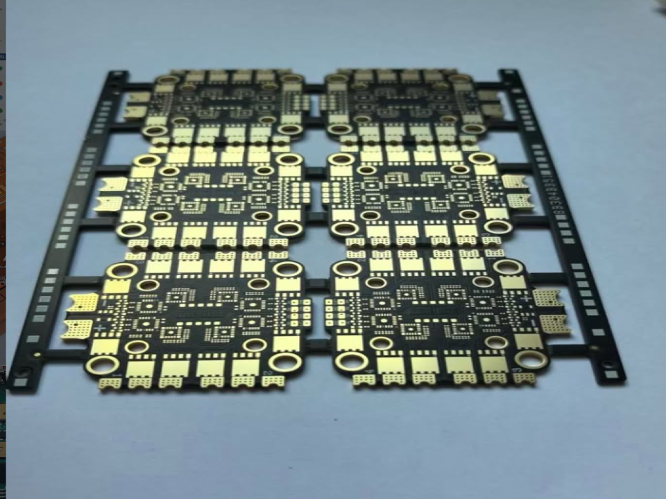
If there’s a BGA field, fine-pitch pads, via-in-pad, blind vias, or HDI routing, I’d look there first because registration movement and Z-axis expansion can turn into field complaints later. A board like an immersion gold HDI multilayer PCB panel doesn’t give you much room for casual material decisions.
Tiny tolerances. Expensive mistakes.
For high-speed or RF-related boards, the question shifts again. Tg matters, yes, but Dk, Df, glass weave, copper roughness, and impedance stability may become louder than thermal rating. That’s why a 6-layer ENIG high-frequency PCB shouldn’t be quoted like a normal digital board just because both drawings say FR-4 somewhere.
And for LED or real heat-spreading work? Don’t force FR-4 to act like aluminum. A double-sided aluminum LED PCB panel exists for a reason. FR-4 can survive heat within limits. It doesn’t magically conduct it away.
The RFQ Is Where the Stackup Usually Gets Damaged
But the factory made it wrong, right?
Maybe. Or maybe the RFQ was already broken.
I’ve seen drawings where one note says “FR-4,” another says “Tg 170,” the email says “standard material okay,” and the buyer’s target price silently says “please don’t make this too expensive.” What is the supplier supposed to do with that? Guess? Many will. Some will guess cheaply.
That’s where a mixed PCB stackup becomes dangerous. Not in the lamination room. Earlier.
Before price is final, ask the boring questions: Is the PCB going through lead-free reflow at around 245°C to 260°C? Any rework cycle? Any heavy copper? Any press-fit connector? Any filled via? Any dense BGA? Any operating temperature above the polite zone? Any customer reliability test that nobody mentioned until after shipment?
Those details decide the FR4 laminate stackup.
Not the shortest quotation.
| Stackup Checkpoint | Why It Matters | What I Would Ask Before Production |
|---|---|---|
| Tg requirement | Controls material behavior after glass transition | Is Tg 130, 150, 170, or above required by design or just copied from an old drawing? |
| Td value | Shows thermal decomposition resistance | Is the PCB exposed to multiple lead-free reflow cycles or repair cycles? |
| Z-axis CTE | Affects via barrel reliability | Are there plated through holes, filled vias, or HDI microvias under thermal stress? |
| Resin system match | Affects bonding and lamination stability | Are high Tg and standard FR-4 from compatible laminate families? |
| Copper balance | Affects bow, twist, and registration | Are plane layers symmetrical, or is copper concentrated on one side? |
| Moisture control | Affects delamination and popcorning | Is baking required before assembly or rework? |
| Surface finish | Affects solderability and pad reliability | Is ENIG, HASL, OSP, immersion silver, or another finish specified? |
This table looks basic. It isn’t.
It’s the difference between “we made samples” and “we can repeat production without praying.”
Standard FR-4 Still Deserves Respect
Not every PCB needs high Tg material. I know, that sentence won’t help anyone sell premium stackups, but it’s true.
A FR-4 universal TV mainboard PCB may work perfectly with standard FR-4 if the thermal load, copper balance, component density, and assembly profile are normal. Same for many interface boards, consumer control boards, and stable low-power products.
Don’t over-engineer boredom.
The problem is copying. A team sees TG170 on one older product and drags it into the next design without checking whether the next PCB has the same operating temperature, layer count, copper balance, or reflow exposure. Then the material spec becomes superstition.
High Tg is not magic powder. It’s a tool.
When Hybrid Stackup Turns Ugly
Hybrid PCB stackup sounds sophisticated. Sometimes it’s just a future failure with better wording.
Different resin systems can cure differently. Prepreg can flow differently. The stackup can move unevenly. Drill smear can change. Inner-layer registration can drift. Bow and twist can creep in when copper balance and material behavior don’t line up.
And the worst part? The PCB may pass bare board electrical test.
Of course it passes. Electrical test doesn’t always tell you whether the via barrel is quietly living under stress, whether the interlaminar bond is marginal, or whether the board will complain after assembly, shipping, heat cycling, vibration, and a few months inside a powered product.
From my experience, this is where cheap mixed stackups become expensive: not in the first PO, but in the second conversation, the one where everyone asks why the return rate is strange.

How to Combine High Tg and Standard FR4 in PCB Stackup
Don’t start with material price. Start with stress.
Map the hot zones, BGA zones, heavy copper areas, connector stress, reflow exposure, and expected operating temperature. Then decide which layers actually need high Tg FR-4 and which can stay standard. If nobody can explain why a layer needs high Tg, maybe it doesn’t.
Keep laminate families compatible. That matters more than people admit.
Use real stackup language: core thickness, prepreg type, copper weight, finished thickness, Tg class, resin system, impedance notes, surface finish, and special process control. “FR-4” is not a stackup. It’s a category label.
And please, keep symmetry in mind. Mixed material plus ugly copper balance is a nice way to invite bow, twist, and registration headaches. The press doesn’t care about your target price. It cares about physics.
For dense or flexible-related assemblies, the material decision may also interact with mechanical movement. A custom flexible circuit PCB with gold pads follows a different reliability logic from rigid FR-4, but the lesson is similar: material choice has to match how the product actually moves, heats, bends, or ages.
Practical Comparison: Standard FR4, High Tg FR4, and Mixed Stackup
| Option | Best Use Case | Cost Level | Main Benefit | Main Risk |
| Standard FR-4 stackup | Consumer, low-power, mature designs | Low | Easy sourcing and stable cost | Weak margin for high reflow or high heat |
| Full high Tg FR-4 stackup | Automotive, industrial, dense BGA, heavy copper | High | Better thermal and dimensional stability | Over-specification if risk is low |
| Mixed FR4 PCB stackup | Selective thermal stress with cost pressure | Medium | Balances reliability and cost | Requires careful laminate matching |
| Non-FR4 thermal substrate | LED, power, heat-spreading products | Medium to high | Better heat path than FR-4 | Different fabrication rules and design limits |
| High-frequency laminate stackup | RF, microwave, controlled Dk/Df circuits | High | Better signal behavior | Not a simple FR-4 cost substitute |
The mixed option looks attractive because it sits in the middle.
That’s the trap.
Middle doesn’t mean easy. It means the factory, engineer, and buyer must agree on exactly what is being mixed, why it’s being mixed, and what inspection proves the decision is safe enough for production.
My Bias: I Don’t Trust Vague “TG170” Notes
Here’s the ugly truth again: “TG170” written alone on a drawing is not a material strategy.
It’s a wish.
A real FR4 PCB stackup decision should include laminate brand or equivalent class, material family, thickness build, copper distribution, surface finish, and assembly expectations. If the board is high layer count, HDI, heavy copper, or impedance controlled, the supplier should review manufacturability before the buyer treats price as final.
Will that slow the quotation down? A little.
Will it avoid the circus later? Often, yes.
For a standard control PCB, normal FR-4 may be enough. For a heat-loaded industrial product, full high Tg may be worth it. For selective risk, mixed stackup can be very good. But if the decision is made only to cut cost, without lamination and reliability review, I’d rather not pretend it’s engineering.
It’s gambling with resin.
FAQs
What is a mixed FR4 PCB stackup?
A mixed FR4 PCB stackup is a multilayer PCB construction that combines high Tg FR-4 and standard FR-4 in one controlled layer structure to balance heat resistance, lamination behavior, Z-axis expansion, production yield, and cost. It works best when the high-stress zones are clearly identified before fabrication.
In plain factory language, it means we don’t pay for premium laminate everywhere unless the PCB actually needs it. But the stackup still needs discipline: compatible resin systems, balanced copper, defined prepreg, and clear assembly temperature assumptions.
When should I use high Tg FR4 instead of standard FR4?
High Tg FR4 should be used when the PCB faces high reflow temperature, repeated thermal cycling, dense BGA packages, heavy copper, elevated operating temperature, or thick multilayer construction where standard FR-4 may lose dimensional stability. It is mainly a reliability margin, not a decoration on the quotation.
If the board is cool-running and simple, standard FR-4 may be fine. If the PCB has ENIG, BGA, HDI, heavy copper, or harsh operating conditions, I’d review high Tg seriously before production.
Can high Tg and standard FR4 be combined in the same PCB?
High Tg and standard FR4 can be combined in the same PCB when the laminate families, Tg values, resin flow, CTE behavior, copper balance, lamination cycle, and inspection method are controlled as one stackup. The risk increases when materials are mixed only for price without engineering review.
The factory should not “just try it.” That phrase scares me. A mixed stackup needs an approved build sheet, not a casual note in an RFQ email.
What is the biggest risk in a hybrid PCB stackup?
The biggest risk in a hybrid PCB stackup is hidden mechanical and thermal stress caused by mismatched resin behavior, Z-axis expansion, copper imbalance, moisture absorption, or weak interlaminar bonding. These issues may not appear during bare board electrical testing but can show up after assembly or field use.
That’s why sample success doesn’t always prove mass production safety. A few good prototypes can still hide an unstable material combination.
Does a mixed PCB stackup reduce cost?
A mixed PCB stackup can reduce cost when high Tg FR-4 is used only in the layers or zones that actually need higher thermal and mechanical stability. The cost benefit depends on material availability, layer count, lamination complexity, inspection needs, and expected production yield.
If the mixed build creates special sourcing, extra press control, or lower yield, the saving may disappear. Cheap on paper isn’t always cheap in production.
Is mixed stack up suitable for high-speed PCB design?
Mixed stackup can be suitable for high-speed PCB design only when impedance, dielectric thickness, Dk, Df, copper roughness, glass weave, reference planes, and laminate consistency are controlled together with the Tg requirement. For high-speed boards, signal behavior may be stricter than thermal behavior.
So don’t call it “FR-4” and stop there. For high-speed work, the laminate is part of the circuit.
Conclusion
Send the Gerber files, target layer count, finished thickness, copper weight, surface finish, impedance notes, operating temperature, assembly profile, and any special reliability requirement.
We can help review whether standard FR-4, full high Tg FR-4, or a mixed FR4 PCB stackup makes better sense for cost, production yield, and long-term reliability.
