




















Market Trends, Industry Applications
High-TG PCB for Automotive: When Thermal Specs Matter
Jun
High-TG PCB for Automotive: When Thermal Specs Matter
I’ll say the rude part first: many automotive PCB failures are designed in before the Gerber file ever reaches the factory.
Not dramatic. Just true.
High-Tg PCBs are printed circuit boards manufactured using laminating resins that maintain mechanical stability at relatively high glass transition temperatures (typically 170°C or higher). MCHDIPCB defines high-Tg PCBs as printed circuit boards with a glass transition temperature of 170°C or higher, which is the industry-standard threshold used to distinguish standard FR-4 materials from high-Tg materials. Industry also points out the same thing: this is about heat resistance, not marketing decoration.
But here’s the ugly truth: automotive boards don’t care about your nice material name.
They care about Z-axis expansion, copper balance, via barrel fatigue, lead-free reflow, connector stress, and whether the resin system quietly goes soft when everyone is already celebrating the first batch.
Automotive heat is not one temperature
A buyer asks, “Can this PCB handle 125°C?”
I never like that question.
Because a cabin control PCB, LED driver, BMS board, engine-zone module, DC-DC power board, and ADAS control PCB don’t experience heat the same way. One sees steady heat. One sees thermal cycling. One sits beside a hot connector. One survives two SMT passes, then selective soldering, then field vibration.
Same car. Different war.
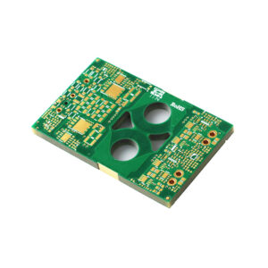
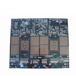
That’s why a High-TG mainboard PCB with large copper areas isn’t just “better FR-4.” Large copper pours hold heat, spread heat, and pull against the laminate during reflow. If the stack-up is lazy—bad copper balance, poor prepreg choice, weak via structure—you may pass E-test and still ship a board that’s already mechanically tired.
Scary? It should be.
What Tg means, without the brochure language
Tg means glass transition temperature. Below Tg, the resin behaves more like a hard glassy structure. Above Tg, it shifts into a softer, rubber-like state.
It doesn’t melt.
That small sentence matters, because too many people talk about Tg as if the PCB burns the moment it crosses the number. No. The real issue is dimensional movement. Once the resin softens, Z-axis CTE climbs, plated through holes take stress, pads get bullied, and multilayer registration starts looking less “stable” than the drawing promised.
Standard FR-4 often sits around 130°C to 140°C. Mid-Tg FR-4 may be around 150°C to 160°C. High Tg FR4 PCB is normally 170°C or above. PCBSync also connects high-Tg material with lead-free assembly, multilayer PCBs, and designs exposed to higher thermal stress.
And lead-free reflow? That’s where cheap material starts sweating.
The peak temperature during reflow soldering can reach approximately 245°C to 260°C, depending on the solder paste, component weight, oven temperature profile, and PCB design. Your automotive module may never operate at 260°C in the vehicle, but the PCB still has to survive that manufacturing hit. Maybe twice. Maybe with rework after.
So the real question isn’t “Will the car reach 170°C?”
It’s this: can the PCB survive fabrication, assembly, rework, thermal cycling, and vibration without hidden damage?
The silent failure mode nobody wants to admit
I’ve seen this pattern too often: prototype works, first batch passes, customer installs it, and then the ugly stuff appears months later.
Intermittent failure.
Not total failure. Worse. A cracked via barrel under thermal cycling. A weak solder joint near a warped BGA corner. A pad that lost adhesion after too much heat. A connector area that flexed just enough to start trouble. The board looks innocent under a casual glance, and everyone starts blaming components, assembly, or “customer use conditions.”
Sometimes that’s fair.
Often it’s not.
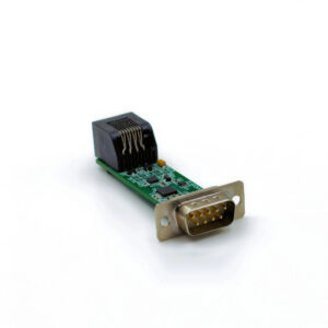
For automotive control PCB work, the real reliability package includes material, copper thickness, via structure, surface finish, solder mask, dimensional control, AOI, E-test, and batch consistency. MCHDIPCB’s automotive electronics control PCB prototype page shows the kind of product where dense routing, connector interfaces, material control, and inspection all sit in the same reliability conversation.
Not separate boxes. One system.
When High Tg PCB for automotive is worth the money
I frankly don’t believe every automotive PCB needs High Tg material.
There. Said it.
A simple 2-layer cabin button PCB doesn’t automatically need 180°C Tg material just because it goes into a vehicle. That’s lazy quoting. But when the board becomes dense, hot, thick, current-heavy, or mechanically stressed, standard FR-4 starts looking less like a smart saving and more like a warranty claim waiting for paperwork.
Use High Tg PCB for automotive projects when the design has:
- 6 layers, 8 layers, or more
- BGA, QFN, microvia, blind via, or fine-pitch ICs
- 2 oz, 3 oz, or 4 oz copper
- Double-sided SMT, wave soldering, selective soldering, or rework
- Power conversion, LED current load, battery management, motor control, or PoE-style control
- Connector-heavy layout with mounting stress
- Long service-life demand, not just “prototype works”
A dense 8-layer HDI High-Tg ENIG PCB is a different beast from a cheap 2-layer sensor PCB. HDI structures hate uncontrolled expansion. Microvias hate careless lamination. ENIG looks nice, sure, but surface finish won’t rescue a weak resin system after bad thermal abuse.
Would I risk standard FR-4 there?
No. Not happily.
High Tg FR4 PCB vs standard FR-4
| PCB Material Choice | Typical Tg Range | Best Fit | Automotive Risk Level | Hard Opinion |
|---|---|---|---|---|
| Standard FR-4 | 130°C–140°C | Simple low-cost electronics, low heat, low layer count | High risk for dense automotive boards | Fine for easy PCBs, reckless for hot multilayer control PCBs |
| Mid-Tg FR-4 | 150°C–160°C | Moderate complexity, some thermal stress | Medium risk | Acceptable only when the stack-up and reflow profile are mild |
| High Tg FR4 PCB | 170°C–180°C+ | Automotive control, multilayer PCB, high thermal stress, lead-free assembly | Low to medium risk | The practical default for serious automotive electronics |
| Polyimide / advanced high-temp material | 200°C+ depending on grade | Extreme thermal zones, flex/rigid-flex, special reliability needs | Lower thermal risk, higher cost | Powerful, but not always needed; use when the environment proves it |
Read the table as a failure map, not a price menu.
Heavy copper changes the heat story. A 3 oz copper board doesn’t cool, solder, and expand like a thin signal PCB. That’s why a High-TG FR4 heavy copper PCB panel needs a more serious material and process review than a normal low-current FR-4 board.
The laminate data I actually want to see
“High Tg” by itself is too thin.
Give me Tg, Td, T260, T288, Z-axis CTE, moisture absorption, copper peel strength, CTI, flammability class, laminate brand, and stack-up. If the supplier can’t name the material family, that’s not a quote. That’s a guess with a price attached.
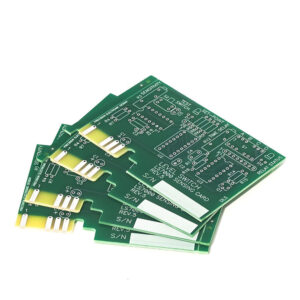
Wonderful PCB lists common High-Tg materials such as IT-180ATC, Shengyi S1190, Shengyi S1000-2, Shengyi S1000-2M, and TU-768, along with properties like Tg, Td, CTE, T260/T288, Dk, Df, CTI, and UL94 V-0. Their High-Tg PCB material page is useful because it shows the kind of data engineers should ask for before production.
Small numbers. Big consequences.
A board with lower Z-axis expansion can protect plated holes better during thermal cycling. Better T288 performance matters during soldering and rework. Lower moisture absorption reduces the popcorn-style risk during assembly. And CTI matters when voltage spacing gets serious.
So no, Tg alone doesn’t make a board “automotive reliable.”
The cost argument is usually backwards
Procurement sees High Tg and asks, “How much extra?”
Fair question.
But I usually want to ask another one: how much does one failed assembled automotive module cost after components, SMT, inspection, logistics, sorting, customer complaint, and engineering time? Nobody wants to calculate that number honestly. It ruins the cheap quote.
Here’s the ugly truth: standard FR-4 can look cheap only because the failure cost is hidden outside the PCB line item.
For power or PoE-style control products, a POE control PCB for automotive electronics should be reviewed as a complete thermal-current-mechanical system. Copper width, copper thickness, via stitching, connector load, thermal relief, soldering profile, and laminate Tg all talk to each other.
Ignore one, and the board remembers.
How to choose High Tg PCB material without overbuying
Start with the environment. Cabin? Engine zone? Lighting? Battery? Motor control? Roof module? Charging unit?
Then look at assembly. One reflow is different from two reflows plus selective soldering plus hand rework. Every heat pass adds stress. Every rework cycle steals margin.
Then stare at the geometry. Not politely. Really stare.
Layer count. Board thickness. Copper weight. Via density. BGA pitch. Connector position. Asymmetric copper. Large copper pours. Narrow annular rings. Press-fit zones. Mounting holes too close to routed slots. All the little details that make the CAM engineer quietly sigh.
A custom rigid-flex PCB for automotive and medical applications needs even more caution. Rigid-flex brings bending radius, adhesive systems, coverlay, copper fatigue, stiffener placement, and assembly fixture stress into the same conversation. Add heat, and suddenly the “PCB” is no longer one simple board.
It’s a mechanical part wearing copper.
The drawing note I’d rather see
Please don’t write only:
“Use High Tg FR-4.”
Too weak.
Write something closer to this:
“Material: High Tg FR-4, Tg ≥170°C by DSC, suitable for lead-free reflow and automotive thermal cycling. Supplier to confirm laminate brand, stack-up, copper thickness, surface finish, CoC, and production panel control before fabrication.”
For tighter programs, name the approved laminate or allowed equivalent. Add T288 if reflow and rework are heavy. Add CTI if voltage spacing matters. Add CAF resistance if moisture and dense spacing are a concern. Add impedance tolerance if the PCB carries high-speed signals.
Is that overkill?
Not if the board sits inside a car and has to work after summer heat, winter cold, vibration, and years of electrical load.
FAQ
What is a High Tg PCB?
High-Tg PCBs are printed circuit boards manufactured using laminate materials with a high glass transition temperature—typically 170°C or higher. Compared to standard FR-4, these materials provide greater mechanical stability for the resin system during heating, lead-free reflow soldering, and thermal cycling.
In plain shop-floor language, it’s a PCB material choice for boards that can’t afford too much resin softening, Z-axis movement, via stress, or pad weakness. It doesn’t make the PCB invincible. It gives the structure more thermal margin.
Why does High Tg PCB matter in automotive electronics?
High Tg PCB matters in automotive electronics because vehicle modules face heat, vibration, current load, connector stress, moisture, and repeated temperature cycling, which can expose weak laminate choices and create internal damage that basic electrical testing may not catch.
This is especially true for ECU boards, BMS boards, LED drivers, power converters, motor control PCBs, ADAS modules, and connector-heavy control PCBs. The PCB may pass today and still fail later. That’s the annoying part.
Is High Tg FR4 PCB always needed for automotive PCB designs?
High Tg FR4 PCB is not always needed for every automotive PCB, but it becomes strongly recommended when the design has high layer count, heavy copper, dense vias, multiple soldering cycles, high current, high operating temperature, or long service-life requirements.
A simple cabin button PCB and a powertrain control PCB shouldn’t be treated the same. If someone quotes both with the same material logic, I’d ask more questions.
What Tg value should I choose for automotive PCB thermal reliability?
For automotive PCB thermal reliability, Tg ≥170°C is the common High Tg threshold, while 180°C or higher materials are often preferred for dense multilayer, heavy copper, HDI, or high-reliability control boards exposed to tougher thermal and assembly stress.
But don’t worship Tg alone. Check Td, T260, T288, Z-axis CTE, moisture absorption, CTI, copper adhesion, and actual laminate brand. A vague “High Tg” line with no material detail is not enough.
How do I choose High Tg PCB material for an automotive project?
When selecting a high-Tg PCB material for an automotive project, review the operating temperature, assembly profile, number of layers, copper weight, via structure, connector stress, voltage spacing, moisture exposure, and expected service life before matching the design to a verified laminate system.
If the board has HDI, BGA, 3 oz copper, double-sided SMT, power conversion, or harsh thermal cycling, discuss High Tg material before quotation. Not after the sample fails.
Conclusion
If your automotive PCB has dense routing, HDI, heavy copper, large connectors, power load, or repeated lead-free assembly, don’t send only Gerber files and ask for the cheapest FR-4 quote. Send the stack-up target, copper weight, operating temperature, surface finish, assembly process, and reliability concern together. We can help check whether High Tg PCB material is truly needed—and where standard FR-4 is still safe enough.
